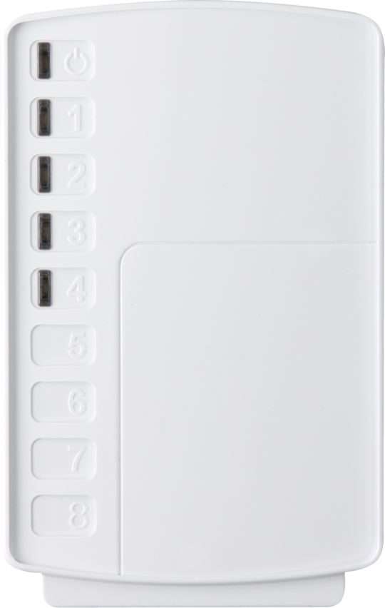
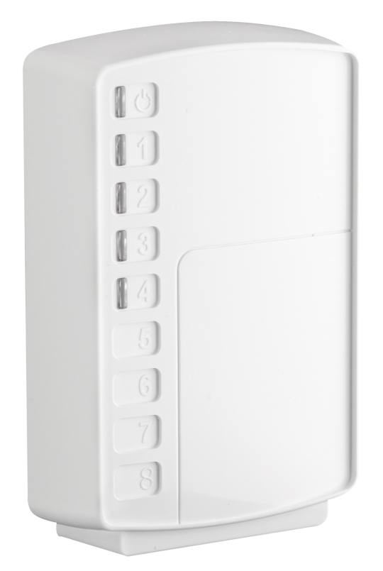
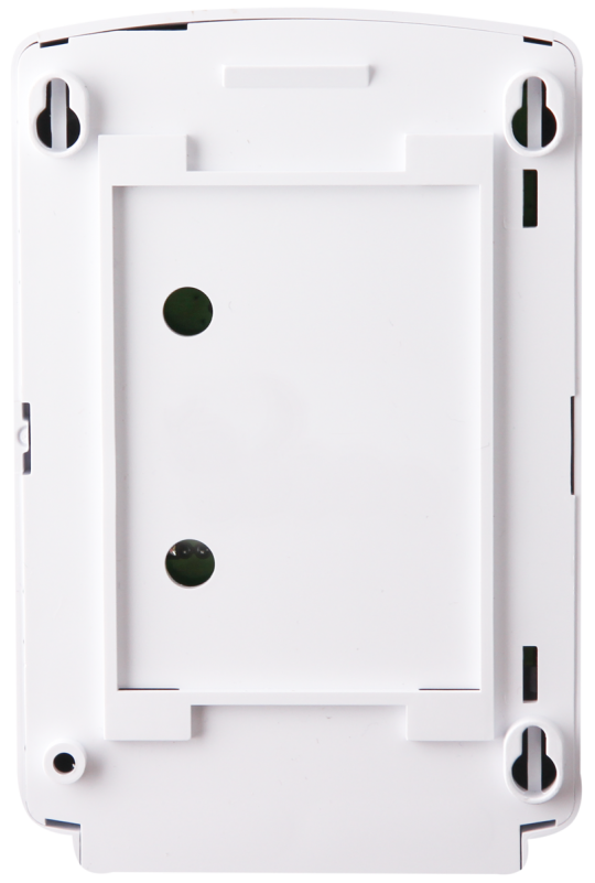
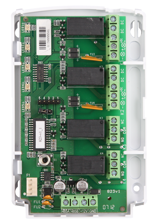
Power relay unit

RU is intended for controlling relay outputs by commands from the control panel via the RS-485 interface.

RU operates in two modes (for switching the load power supply according to the commands of the Control panel):
   - with circuit integrity control (relay 1, 2)
   - high-voltage circuit switching (AC/DC 250 V) without circuit continuity
control (relay 1-4).

1. RU is intended for controlling relay outputs by commands from the control panel via the RS-485 interface.

2. RU operates in two modes (for switching the load power supply according to the commands of the Control panel):
   - with circuit integrity control (relay 1, 2)
   - high-voltage circuit switching (AC/DC 250 V) without circuit continuity control (relay 1-4).

3. The source of commands for RU is partitions of the Control panel.

4. RU can be controlled by only one Control panel.

5. Up to 64 RU can be connected to one Control panel via RS-485 interface.

6. Assigning to a specific partition number, types of processed notifications and the mode of operation of each relay is performed during system outputs configuration from the Control panel or PKM menu.

7. RU provides integrity control of the RS-485 interface, activation of 1-4 type of alerts.

8. To power RU, you can use a power supply with a voltage from (11.0± 0.5) V to (15.0 ± 0.5) V. Using a linear resistance of one wire core of 100 Ohm/km, the length of the supply wire should be no more than 25 m (for example, when using 2×0.2 wire, it is permissible to use a supply wire up to 25 m long; wires should be no more than 40 m).

Features

  • 4 outputs:
    - 2 (K1 and K2) with open and short circuit control,
    - 2 (K3 and K4) without control;
  • when the control circuit of the outputs K1 and K2 switched only for closing circuits is on, the voltage is switched from an external power supply DC 5 - 30 V to the output to power the load Rn (when the output is closed, voltage is supplied);
  • when the control circuit of the output circuits K1 and K2 is switched off, switching of AC/DC voltages up to 250 V is provided;
  • uncontrolled outputs K3 and K4 provide switching of AC/DC voltages up to 250 V by switching contacts;
  • outputs are switched on/off (for K1 and K2) and switched (for K3 and K4) by the control device.
Name Description
Supply voltage from 10.5 to 15.5 V DC
Max current consumption 170 mA
RS-485 interface line length 1000 m
Relay 1, 2 Characteristics in continuity mode load circuits:  
- switching voltage range (at the Vdc terminal) from 5 to 30 V
- switched current range from 0.6 to 2.0 A
Minimum switching current 0.6-0.5 mA
Load shedding current at short circuit 2.0+0.5 A
Relay 1, 2 in non-continuity mode specifications:
load circuits and relays 3.4 (NO-COM-NC):
 
- maximum switching voltage (AC) 250 V
- maximum switching voltage (DC) 30 V
- maximum switched current 3 A
- maximum switching power 750 W
Overall dimensions 120.5х79х30.5 mm
Weight 0.12
Operating conditions  
Temperature from -30 to +55 °С
Relative air humidity up to 93% at +40°С (without moisture condensation)

Manuals 

823-v2_0_en.pdf