Addressable Relay Unit

Designed for:
- Control the communication line and managing devices of the alerting system and control evacuation of people in case of fire;
– Control and start of automation control cabinets (signals "Failure", "Emergency", "Automatics disabled" and "Smoke exhaust Fan" (pump, lock) activated);
– Control and service fire automatics powered by 12 V or 24 V;
– Transmission of signals through an intermediate relay device to the inputs of elevator controllers, voice alerting units, etc.);
– Control through the built-in two AL (Zone 1 – Zone 4) of addressable fire detectors, intrusion, technological devices (including those powered by AL) and transmission of notifications via SLC through RPA to the Control Panel.

1.1 BPA is designed for:
– control the communication line and managing devices of the alerting system and control evacuation of people in case of fire;
– control and start of automation control cabinets (signals "Failure", "Emergency", "Automatics disabled" and " smoke exhaust Fan (pump, lock) activated);
– control and service fire automatics powered by 12 V or 24 V;
– transmission of signals through an intermediate relay device to the in-puts of elevator controllers, voice alerting units, etc.);
– control through the built-in two AL (Zone 1 – Zone 4) of addressable fire detectors, intrusion, technological devices (including those powered by AL) and transmission of notifications via SLC through RPA to the Control Panel.

1.2 BPA is designed to operate in SLC formed by RPA.

1.3 The number of BPAs registered in the Control Panel is up to 96 pcs.

1.4 BPA provides protection of control outputs OUT1, OUT2 against overloads, polarity reversal, voltage surges.

1.5 In the initial state, reverse polarity voltage is applied to the outputs of the BPA, it is necessary to protect the connected load sensitive to polarity from reverse voltage.

1.6 The outputs OUT1, OUT2 can be operated with or without control of the integrity of the line (depending on the configuration).
When outputs are operated with line integrity control, it is necessary to connect the terminal elements of the output from the delivery set to the terminals OUT1, OUT2.

1.7 BPA provides:
a) control of the power supply at the inputs U1, GND, U2, "+", "-";
b) switching the input voltage from 10.5 to 28.7 V from inputs U1, U2 to outputs OUT1 and OUT2 with switching current of each output up to 1.25 A;
c) control of the load line of the outputs OUT1 and OUT2, separately for open and short circuits, and transfer to the Control Panel infor-mation about the integrity of the load line;
d) control of the state of 4 alarm loops of the following types: security, fire thermal with double actuation, fire smoke with double actuation, fire com-bined with single actuation and technological with short circuit (Open cir-cuit) control;
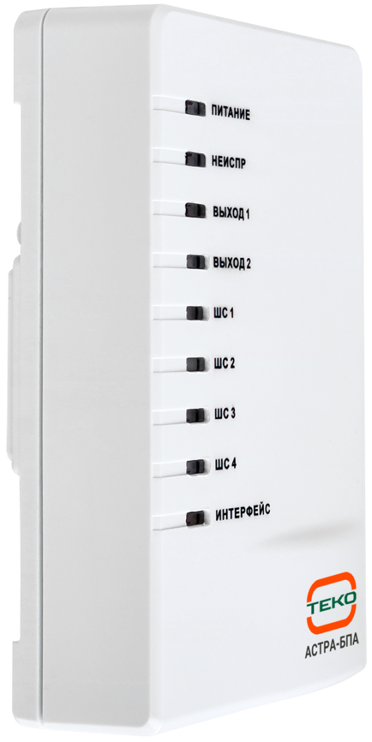
e) light indication of the BPA operation, the status of the outputs, SLC and AL.

1.8 The power supply of the address part of the BPA is carried out only from the RPA via the SLC power line (terminals "+", "-").

1.9 The power supply of the outputs and AL of the part (outputs, AL) is carried out only from an external power supply of 12 V or 24 V D.C.

Features

  • operating in the signaling line (SLC) formed by the signaling line extender (RPA);
  • control of the load line of the outputs OUT1 and OUT2, separately for open and short circuit, and transfer to the Control Panel of information about the integrity of the load line;
  • protection of control outputs OUT1, OUT2 against overload, polarity reversal, voltage surges;
  • operation of outputs OUT1, OUT2 (depending on setting) with or without line integrity control. When outputs are operated with line integrity control, terminal output elements from the delivery set are connected;
  • control of the presence of power supply at the inputs U1, GND, U2, "+", "-";
  • switching of input voltage from 10.5 to 28.7 V from inputs U1, U2 to outputs OUT1 and OUT2 with switching current of each output up to 1.25 A;
  • control of the status of 4 alarm loops of the following types: security, double event fire alarm, fire combined single event, emergency;
  • led indication of the operation of the BPA, the status of the outputs, SLC and AL;
  • DIN rail installation support.
Name Description
Supply voltage 10.5 to 28.7 V DC
Average current consumption* (AL1-AL4 is off.) at 12 (24) V: 20 mA
without line control (OUT1, OUT2 off) 14 (15) mA
with line control:  
OUT1, OUT2 off 16 (17)
OUT1 on, OUT2 off 19 (20)
OUT1 off, OUT2 on 19 (20)
OUT1, OUT2 on 23 (24)
Inherent control current (reverse polarity)* of outputs OUT1, OUT2 in the "Off" state (current consumption of terminal output element) at voltage 12 (24) V 1 (3) mA
Connecting each loop increases the average current consumption at voltage 12 (24) V:  
Standby mode for 7 (10) mA
Fire mode for 12 (16) mA
Max. current consumption voltage 12 (24) V 73 (94) mA
Max. current consumption with connected load 2.6 A
Max. cable cross section for connection to terminal 2.5 mm2
Current consumption on the SLC supply line 1 mA
Boot time 10 sec
Overall dimensions 135x85x39 mm
Weight 0.35 kg
Operating conditions  
Temperature from -30 to +55 °С
Relative air humidity up to 93% at +40°С (without moisture condensation)

Manuals 

BPA-v1_1_en.pdf